Robotics
Quadruped Robot
A 3D-printed quadruped with 12 LX-16A serial servos. Python handles gait generation, per-leg inverse kinematics and PID body levelling from an MPU-6050 IMU.
- Python
- Inverse kinematics
- PID
- IMU
- LX-16A servos
- 3D printing

What it is
A 12-servo quadruped I designed and printed, used to learn leg inverse kinematics, gait generation and closed-loop balancing. The control code is Python on a Raspberry Pi-class board. It drives LewanSoul LX-16A serial bus servos over a UART and reads an MPU-6050 IMU for body orientation.
Video demonstrations
 Play: Walking — basic gaits and movement patterns
 Play: Touch sensitivity — reacting to external forces
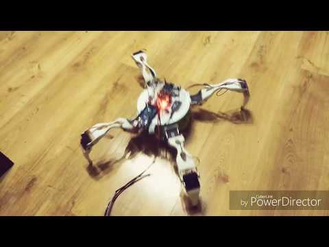 Play: First version of the robot and early testing
 Play: Rig test of an alternative leg design
Hardware and software
| Item | Detail |
|---|---|
| Actuators | 12 × LX-16A serial bus servos, 3 per leg |
| IMU | MPU-6050, Kalman-filtered orientation |
| Controller | Raspberry Pi-class SBC |
| Frame | Custom 3D-printed |
| Software | Python, PySerial, simple-pid, Matplotlib for tuning plots |
Control architecture
The code is split so that motion commands, geometry and servo I/O live in separate modules:
- Main loop (
main_gyro_002.py): entry point; reads keyboard input and the IMU. - Overlord (
Overlord.py): turns commands such as “walk forward” into per-leg foot trajectories (the gait). - Runner (
Runner.py): single-leg inverse kinematics, from foot position to servo angles. - PVector (
PVector.py): body orientation; applies the PID rotations to the foot positions. - Gyro and PID (
gyroscope.py,pid_package.py): IMU data feeds X- and Z-axis PID loops. - LX16A (
LX16A.py): low-level serial servo driver.
Inverse kinematics
Each leg has three joints. Runner.step() takes a foot position {X, Y, Z} in the leg frame and solves the hip angle from the X/Z projection, then the two remaining joints from the triangle formed by the upper leg (L1), lower leg (L2) and hip-to-foot distance (L4) using the law of cosines. Link lengths are in millimetres.
def step(self, X, Y, Z):
    L0 = 56
    L1 = 202.240
    L2 = 173.215

    sqrtZX = (Z * Z) + (X * X)
    T1 = math.atan(Z / X)

    X0 = math.sin(T1) * L0
    Z0 = math.cos(T1) * L0
    X = X - X0
    Z = Z - Z0
    L5 = math.sqrt(sqrtZX)
    L4 = math.sqrt((Y * Y) + (L5 * L5))
    K1 = math.acos(L5 / L4)
    PowL2L4 = (L2 * L2) + (L4 * L4)
    PowL1 = L1 * L1
    subL2L4L1 = PowL2L4 - PowL1
    K2 = math.acos(subL2L4L1 / (2 * L4 * L2))
    K3 = K1 + K2
    K5 = math.acos(((L1 * L1) + (L2 * L2) - (L4 * L4)) / (2 * L1 * L2))
    K6 = K3
    T2 = 3.14159 - (K5 + K6)
    T3 = 3.14159 - K5

    # ... conversion to servo values ...
    return self.pos
Balancing
Two PID loops, one per tilt axis, take IMU roll and pitch and output a body rotation. The rotation is applied to all four foot positions through PVector, and the IK then turns the new foot positions into servo angles. The loops run at a 5 ms sample time with Kp = 0.04, Kd = 0.02 and no integral term. Output is clamped to ±35° so a bad reading can’t command an extreme pose.
def keepSafe():
    pidX = PID(0.04, 0, 0.02, setpoint=0, sample_time=0.005)
    pidZ = PID(0.04, 0, 0.02, setpoint=0, sample_time=0.005)
    pidX.output_limits = (-35 / 57.2958, 35 / 57.2958)
    pidZ.output_limits = (-35 / 57.2958, 35 / 57.2958)

    for i in range(0, 3000):
        vX = data_b[1]
        vZ = data_b[0]

        controlX = -pidX(vX)
        controlZ = -pidZ(vZ)

        vector.rotateZ(controlZ)
        vector.rotateX(controlX)
        executeBase(vector.result())